9.4. Properties
Even if all-ceramic restorations meet aesthetic requirements very well, their most significant disadvantages are their tendency to break. In this direction, the resistance of full ceramic crowns varies depending on various factors. These are the factors such as the properties of the preparation, restoration design, ceramic materials used, infrastructure type, its thickness and length, infrastructure and superstructure connection, crown margin, cementation technique.
Preparation properties: Considering the conventional principles of preparation for full ceramic restorations is important not only for retention but also for stress distribution of the restoration during the dynamic loading. The restoration should be prepared in accordance with the physiological crown contours in order to provide ideal aesthetic features and sufficient resistance. In other words, sufficient cutting should be made in terms of proper restoration. At least 1.2-1.5 mm cutting should be made in enamel and dentin on axial surfaces and 1.5-2 mm cutting on occlusal and incisal surfaces in order to provide sufficient space for infrastructure material and superstructure ceramics. The axial angle of the crown should be applied as 5-6˚. The clinical length of the support should be 4 mm minimum. The biological limits of the dental pulp during gear cutting should be examined.
Restoration design: Fixed denture prosthesis infrastructures can be designed by using conventional waxing technique or computer-aided design (CAD). CAD/CAM zirconia dental infrastructures are acquired by two different techniques as in "soft milling" of partially sintered blocks or in "hard milling" of fully sintered blocks. CAD software programs enable the design of the fixed denture prosthesis infrastructure in accordance with the requirements of the material used.
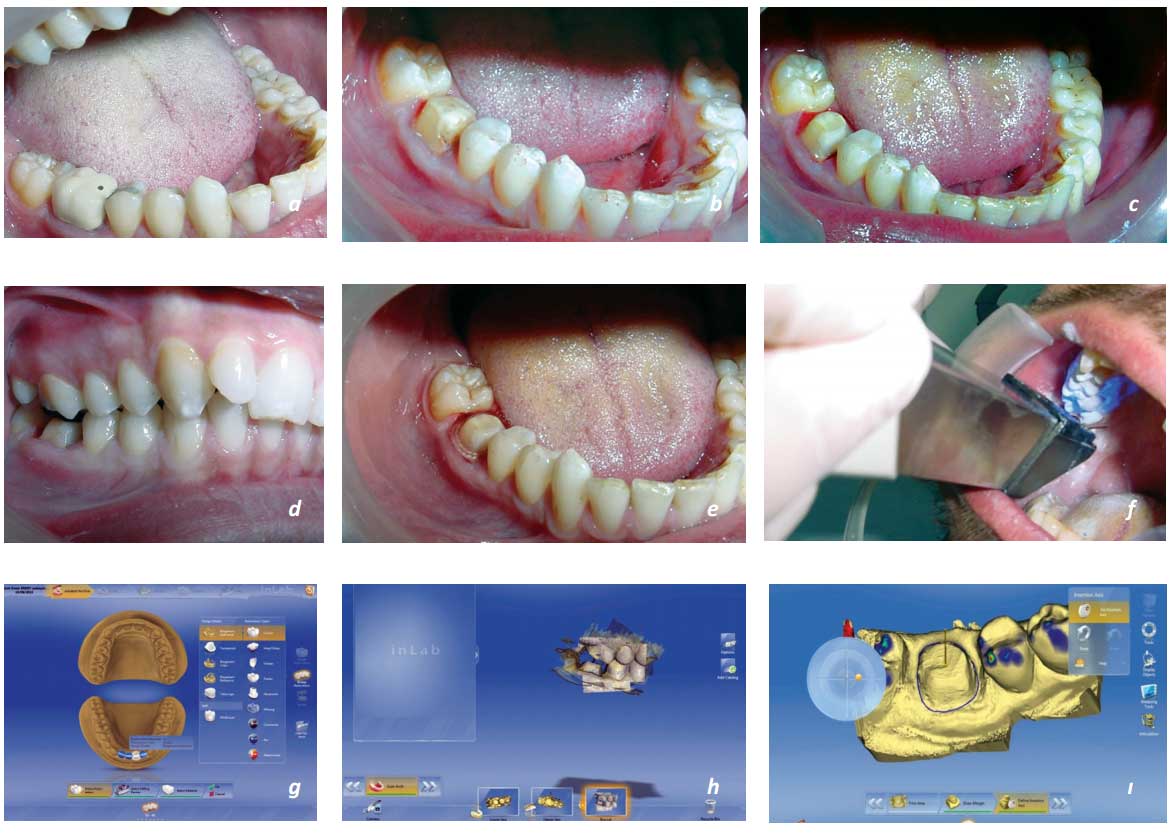
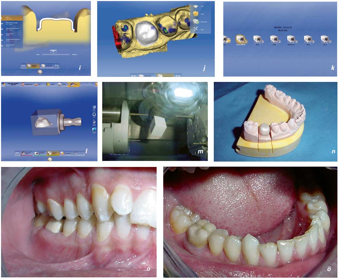 Figure 9.2 a,b. In the mandibular right 1st molar tooth, it has been decided to change the existing metal-supported ceramic crown with a full ceramic crown and it was removed. c,d. Preparation was corrected, e. after retraction process f. it was scanned with Cerec CAD/CAM* system by using intraoral camera optically, g, h, ı, i, j. measured models were transferred to the computer in three dimensions. After the tooth and its restoration type were determined in the software system, the margin drawing was made. According to the closing correlation and the entry way, the models got a suitable location and the parameters of the designed restorations have been determined as required. After the completion of the contour corrections and controls required for the core structure design in the system, k. the selection of the suitable material (InCoris ZI)* and the block size was made for the production of restoration design which was determined. l. Then a semi-sintered InCoris ZI* block is placed into the Cerec milling device (inLab MC XL)*. m, n, o . After the milling process, the core structure with the sintering process completion and ö. Feldspathic veneer porcelain were delivered to the patient by making necessary corrections on it.
Cercon**, Lava*** and Procera Zirconia zirconia blocks, also called "Green stage" (these blocks are obtained by compressing the zirconia powder with a cold isostatic pressing process) are processed by milling technique with carbide mills in a dry environment. The features of this process are that it shows a risk of a less milling time and lower cracks. The sintering process performed after the milling process, accrues at 1500˚C. In the partially sintered In-Ceram, Cerec, Everest***** and Precident DCS zirconia blocks, the milling process is performed with carbide mills under cooling.
The features of this process are similar to the other. However, in the fully sintered zirconia blocks such as Everest and Precident DCS, the milling process is performed under cooling with diamond mills. This kind of milling process requires more time and is expensive, but the advantage is that it does not show sintering shrinkage.
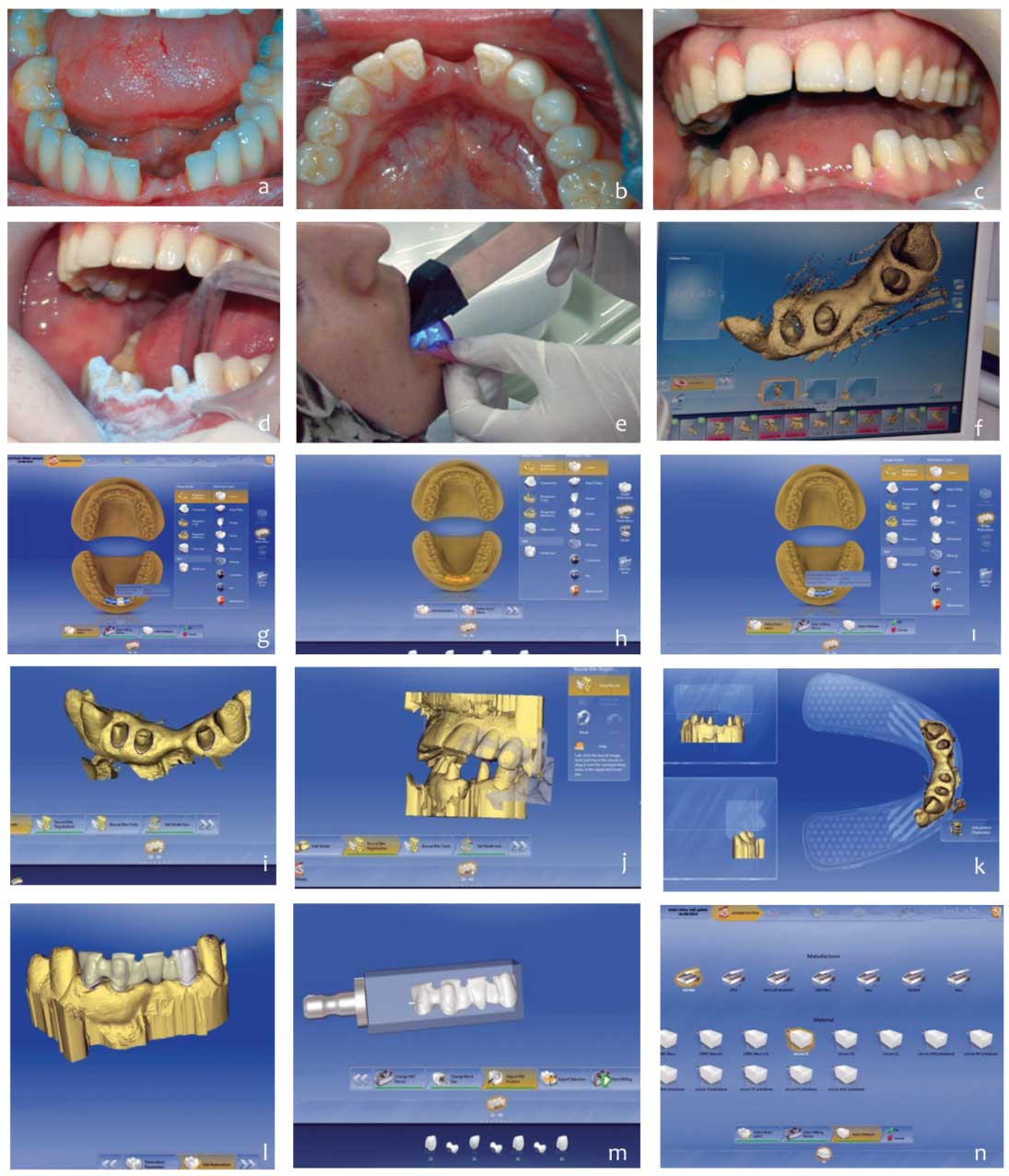
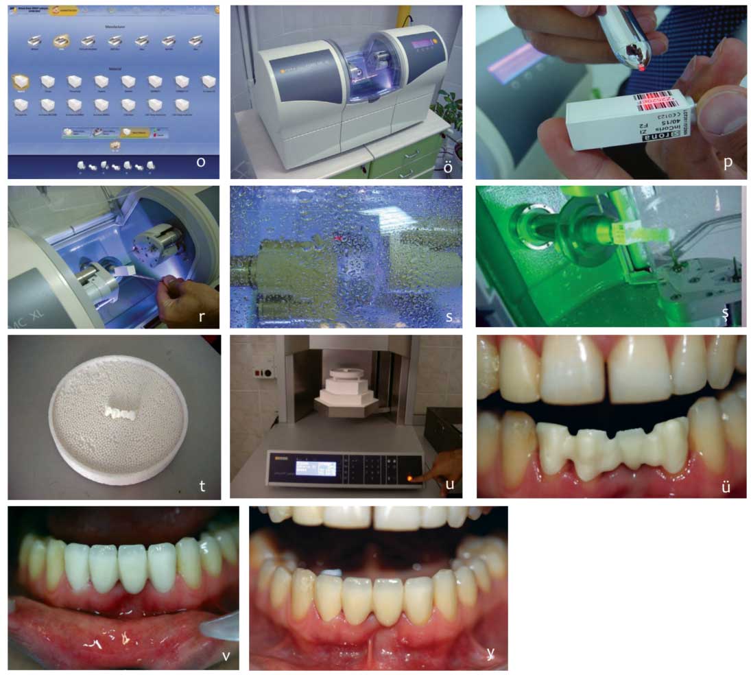
Resim 9.3 a,b.Since the patient with zirconia adhesive bridges supported by mandibular left lateral and right central teeth has both aesthetic and functional dissatisfaction, it was decided that existing missing teeth would be restored with a zirconia full ceramic bridge supported by right central-lateral and left lateral teeth after the clinical and radiological evaluations made. c,d. After the teeth preparation, it was scanned with Cerec CAD/CAM* system by using intraoral camera optically and measured models were transferred to the computer in three dimensions. e,f,g,h,ı,i. After the anchorage and body of the existing restoration were determined in the software system, the margin drawing was made. According to the closing correlation and the entry way, the models got a suitable location and the parameters of the designed restorations have been determined as required. j,k. After the completion of the contour corrections and controls required for the core structure design in the system, l,m. the selection of the suitable material and the block size was made for the production of restoration design which was determined. n. Then o. a semi-sintered ö. zirconia block is placed into the Cerec milling device. p,r. Core structure obtained after the milling process resulting in 15-20 minutes s, ş. Was sintered in the sintering kiln (Sirona inFire HTC Speed)* at 1150 ° C for 12 hours. t. The core structure which was tested in the patient’s mouth, u,ü. Was sent to the laboratory for the application of feldspathic veneer porcelain by taking measurement and v, y. then necessary corrections were made and implemented.
Cercon system, Precident DCS and Lava systems that require conventional waxing techniques, use a different CAD technology with different properties and design options. When the infrastructure design is completed, the information for the production of the infrastructure is transferred to the milling unit. In other words, the data is transferred from CAD unit to CAM unit or the conventional waxing sample is scanned. The production of the infrastructure can be made in two ways. In the first method, the core part is milled and sintered more voluminously than partially sintered prefabricated ceramic blocks and reaches to the demanded final dimensions by 20-25% shrinkage. In the second method, the core part is milled in the demanded dimensions from the fully sintered prefabricated ceramic blocks.
Ceramic material used: Which ceramic material will be used in restoration should be decided by considering the case and material properties to be implemented. The fracture resistance of glass ceramic and alumina ceramics is weaker than zirconia ceramics. For this reason, while these ceramic types are preferred in the anterior region and up to three-member restorations, zirconia ceramics can be used in posterior and multi-member restorations due to their superior properties such as their high chemical and dimensional stability, mechanical durability and fracture resistance.
Zirconia ceramics are 6 times stronger than feldspathic porcelain and 2 times stronger than alumina in terms of fracture and flex resistance. The final point in the search for the ideal infrastructure for full ceramic restorations is yttrium tetragonal zirconia polycrystalline (Y-TZP) based ceramics. The flex resistance of Y-TZP is 900-1200 MPa and fracture resistance is 9-10 MPa. This is almost 2 times of alumina-based ceramics and 3 times of lithium disilicate based ceramics
Infrastructure form: The connection regions are the lowest resistant region of the restoration. Since they are faced with stress-type strengths, the flex resistance should be enough to resist occlusal loads. The fracture resistance in full ceramic restorations is affected by the length of the body, the shape, location and size of the connection zones.
Table 9.1 Commercial examples of zirconia infrastructure produced with CAD/CAM*
| Commercial Examples | Zirconia block type | Milling Process | Features |
|---|---|---|---|
| Cercon (Degudent), Lava (3M ESPE) | "Green stage" | Carbide milling in dry environment | Less milling time Less crack risk Sintering at 1500°C after milling |
| In-Ceram (VITA), Cerec InLab (Sirona), Everest (KaVo), PrecidentDCS (DCS) | Pre-sintered | Carbide milling under cooling | Less milling time Less crack risk Sintering at 1500°C after milling |
| Everest (KaVo), PrecidentDCS (DCS) | Fully-sintered | Diamond milling under cooling | More milling time High cost No sintering shrinkage |
Zirconia bridge infrastructures require less space for connections than other systems due to their mechanical and physical superiority. Fracture of zirconia fixed restorations is associated with poor connection height.
Infrastructure thickness is also a factor affecting the success of the restoration. For this reason, the thickness and shape of the infrastructure should be suitable for obtaining an equal thickness and providing sufficient support in the superstructure ceramic. Generally, the manufacturers indicate that the core structure should be in a thickness of 0.3 mm minimum in the anterior region and 0.5 mm in posterior region to prevent the deformation.
It is shown with the research that surface area of the connections should be 6-16mm2 and connector surface area should be 11mm2 or more so that 5-member zirconia infrastructures can withstand the loads.
Table 9.2 Fracture resistance values of the ceramics**.
| Structure | Ceramic | Fracture resistance |
|---|---|---|
| Feldspathic |
Vitablocs Mark II Cerec in-Lab Blocks Vitablocs TriLuxe |
152 MPa 152 MPa 152 MPa |
| Leucite |
IPS Empress Esthetis KaVo Everest G Blank Ivoclar ProCAD IPS Empress CAD IPS e.max Press |
160 MPa 125 MPa 140 MPa 160 MPa 350 MPa |
| Glass infiltrated |
In Ceram Spinell In Ceram Spinell CAD CAM In Ceram Alumina InCeram Alumina CAD CAM In Ceram Zirconia In Ceram Zirconia CAD CAM |
350 MPa 350 MPa 500 MPa 500 MPa 600 MPa 600 MPa |
| Aluminum oxide |
Vita In Ceram 2000 ALCubes Procera allCeram |
152 MPa 152 MPa |
| Aluminum oxide |
3M ESPE Lava Zirconia Vita In Ceram 2000 ALCubes Cercon Zirconia Procera AllZircon Kavo Everest Z- Blank |
900-1200 Mpa |
Tablo 9.3 *Properties of various zirconia infrastructures used in fixed-partial dentures .
| System | Core Material | Bending Resistance (MPa) | Fracture Durability (MPa/m ½) | Connection Surface Area (mm²) |
|---|---|---|---|---|
| In-Ceram Zirconia (VITA) | Glass infiltrated alumina and 35% partially stabilized zirconia | 421-800 | 6.0-8.0 | 12-20 |
| Cercon (Dentsply/ Ceramco) | Y-TZP | 900-1200 | 9.0-10.0 | 7-11 |
| DCS Precident (DC) | Y-TZP | 900-1200 | 9.0-10.0 | 9.0-10 |
| Lava (3M ESPE) | Y-TZP | 900-1200 | 9.0-10.0 | 9.0-10 |
Infrastructure and superstructure connection: The success of full ceramic systems is substantially affected by the infrastructure and superstructure connection. The ratio of the thickness of the ceramic infrastructure to the thickness of the superstructure porcelain is the main factor which determines the crack propagation and possible failures. It should be provided that these layers are thickened, and the superstructure porcelain is exposed to the pressure stresses and infrastructure ceramic to the tensile stresses. While the thickness of the ceramic infrastructure material is increased, it should be ensured that the restoration is not much contoured or that no more substance is removed from the tooth.
Infrastructure and superstructure connection is affected by infrastructure type, surface application processes in the infrastructure, coloration method of the infrastructure, cracks occurring in the restoration during the production and shrinkage occurring during the cooking of the superstructure ceramic. The lowest connection resistance between the full ceramic systems is seen in Y-TZP infrastructures. This situation is developed out of that the mechanical properties of the Y-TZP and the superstructure ceramics are considerably different and that the surface roughening is more difficult in the Y-TZP ceramics compared to the other ceramics.
When roughening is made by sandblasting on the surface of infrastructures milled in CAD-CAM systems, the retention is more, and sandblasting creates more roughness in colour blocks compared to white blocks and increases the crack formation. However, the application of colorant liquids to the untreated infrastructure and the pressing of the superstructure decreases the connection resistance and increases the crack formation in the Y-TZP infrastructures.
When the difference between the fracture and flex resistance between infrastructure and superstructure is high, the fracture starts from the weakest region. It has been found that the weakest region in the Y-TZP infrastructure-restorations was superstructure or infrastructure-superstructure connection zone. However, when the difference in thermal expansion coefficient between the infrastructure and the superstructure is high, the fracture resistance of the restoration is also affected negatively.
Crown edge: Edge fit (marginal fit) is one of the main criteria for evaluating the clinical success of the restoration. When the infrastructure margin fit was evaluated, it was determined that the infrastructures formed with CAD-CAM were than the conventional metal-supported restorations.
In the restorations, the step width should be equally prepared. It is recommended that this step width should be 0.8-1.2mm. It is indicated that the step shape should be chamfer or shoulder with internal angles rounded in order to ensure the proper distribution of occlusal stresses to the anchorage during the operation of the fixed dentures.
At the gingival level or subgingival marginal termination design should be created. The clinically acceptable value of the marginal range is up to 120 µm. Weak marginal fit causes to dissolution of bonding cement, plaque accumulation in this region, marginal leakage, secondary cavities and failure of crown as a result of all of them.
Processes made at the beginning of the unit or during the use of CAD-CAM systems in the laboratory environment, deterioration of marginal fit problem may be encountered. These problems can be caused by restrictions on the scan tools or milling machines. At the same time the experience of the physician and technician plays a significant role at this stage. Systems using the surface contact tip do not allow the proxima retantif structures to be created at a width of less than 2.5 mm and a depth of more than 0.5 mm.
Light transmittance of all-ceramics:
Some physical properties should be considered to achieve a good aesthetics with zirconia ceramics. For an ideal aesthetic, it may not be suitable to use core materials containing zirconia in areas where translucency (light transmittance), ie. transparency is very important. Because, zirconia has an opaque colour. This is an advantage when a colour of tooth or a metal post is masked. However, if transparency is necessary, lithium disilicate or alumina ceramics should be preferred instead of zirconia. It has been shown that the translucency property of Empress 2 dentin core material is significantly higher than In-Ceram Alumina and In-Ceram Zirconia and Cercon which are two opaque ceramic core materials.
Especially in zirconia-based ceramic systems, minimal thickness is required due to the opaque infrastructure and dentine and enamel ceramics are used to reduce this opaque appearance. Today, most of the manufacturers produce liner materials to improve the properties of bonding to Y-TZP ceramic systems’ dentin, fluorescence and brightness of colours. Although these liners do not provide a major contribution to the bonding, it can increase wettability and reduce the possible interactions with Y-TZP. The radiopacity of the zirconia ceramics facilitates to determine the marginal fit (particularly, in the subgingival end line) in radiographic evaluation.
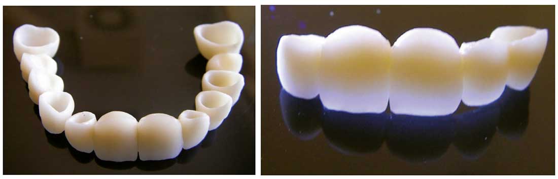 Figure 9.4 a, b. The limited light transmittance of zirconia ceramics restricts also the aesthetic.
* Sirona Dental System, Bensheim, Germany
** Cercon,DeguDent, Hanau-Wolfgang, Germany
*** 3M ESPE USA
**** Nobel Biocare, Goteburg, Sweden
***** KaVoDental, Biberach/Riß, Germany
****** DCS Dental, Allschwil, Switzerland